A chip receives new firmware from Flash, one piece at a time. The system needs the SHA-256 digest of the whole image, not separate digests for its pieces. It cannot discard the final incomplete block.
Software arranges these steps inside one function call. In hardware, you assign each job: who pads the last block, who keeps the previous result, and who holds the next block while the core is busy? Those decisions determine storage and interface behavior.
This lesson builds a SHA-256 iterative block core. It accepts an already-padded 512-bit block, reuses one circuit for 64 rounds, then accumulates the result. Follow the data first, then attach the equations. You need basic synchronous logic, bit operations and Verilog.
The deliverables are a design explanation, interface/timing contract and executable reference model. RTL fragments illustrate important connections; they are not a complete synthesized, timing-closed or certified IP. For the security concepts, start with the SHA classroom. Compare this design with the AES RTL guide once the dataflow is clear.
1. SHA-2 is a family; SHA-256 is our starting point
SHA-256 uses 32-bit words, 512-bit input blocks and a 256-bit digest. FIPS 180-4 defines its functions, constants and processing rules. We implement this member first rather than mixing several algorithms into the first controller.
| Member | Word | Input block | Rounds | Digest |
|---|---|---|---|---|
| SHA-224 | 32 bits | 512 bits | 64 | 224 bits |
| SHA-256 | 32 bits | 512 bits | 64 | 256 bits |
| SHA-384 | 64 bits | 1024 bits | 80 | 384 bits |
| SHA-512 | 64 bits | 1024 bits | 80 | 512 bits |
| SHA-512/224, SHA-512/256 | 64 bits | 1024 bits | 80 | 224 / 256 bits |
These variants are not just output-width switches. SHA-224 has different initial values from SHA-256. SHA-512/256 is not ordinary SHA-512 with its output simply truncated to 256 bits.
SHA-256 does not encrypt data into 256 bits. It produces a fixed-size digest and has no decryption key. A fixed-length digest cannot uniquely represent every possible message. Ordinary SHA-256 has no secret-key input: the K[t] values below are public round constants, not keys.
For firmware, a digest can be compared with a trusted expected value. If an attacker can replace that value too, hashing alone does not authenticate the publisher. Signature verification and trusted metadata belong to the surrounding system; this lesson focuses on computing the correct digest.
2. TOP view: separate message preparation from the core
Use two layers. The outer layer knows the original message length and where the message ends. The inner core processes 512-bit blocks and knows whether each is the first or last padded block.
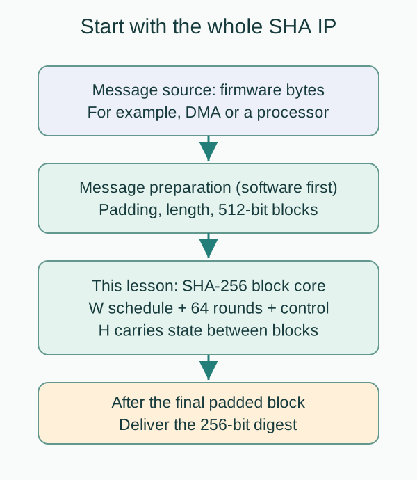
The message-preparation layer pads the message, encodes its original bit length and forms blocks. It can eventually become a streaming hardware wrapper. For the first design, prepare blocks in software or the testbench so padding errors do not obscure core errors. An already-padded block core is not yet a complete arbitrary-byte streaming SHA IP.
Inside the core, the W scheduler supplies one 32-bit word per round. The round datapath computes the next a–h values. The H registers preserve the chaining state across blocks. The controller coordinates acceptance, rounds, accumulation and output. Give these roles distinct names instead of calling every register “state.”
Follow one complete message
For abc, the preparation layer produces one 64-byte block and marks first=1, last=1. The core captures it, loads the initial values, then completes one round per cycle for 64 rounds. It must then add the working result back to the original H values: feed-forward. Only after that step is the digest valid.
For a two-block message, the first result stays in H and becomes the starting point for the second block. Do not restart the second block from the initial values or concatenate two independent hashes. If the final digest’s consumer stalls, the core holds both the digest and valid until the transfer occurs.
3. Padding: who handles an incomplete final block?
For SHA-256, the original bit length L must be less than 2⁶⁴. Append one 1 bit, then k zero bits so that (L + 1 + k) mod 512 = 448. Finally append L as a 64-bit big-endian bit count. It excludes the padding; do not substitute the number of bytes. See FIPS 180-4 §5.1.1.
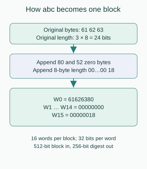
This introductory wrapper handles byte-aligned messages, so appending the 1 bit begins with a 0x80 byte. abc is 61 62 63, with L=24. Append 80, 52 zero bytes and 00 00 00 00 00 00 00 18.
| Original length | Padded blocks | Reason |
|---|---|---|
| 0 bytes | 1 | Even the empty message needs padding and length |
| 55 bytes | 1 | 55 + 1 + 8 fits exactly |
| 56 bytes | 2 | The length field no longer fits in the first block |
| 63 bytes | 2 | Padding and length require another block |
| 64 bytes | 2 | An aligned message still needs padding |
Thus block_last identifies the last padded block, not necessarily the last block containing original data. The distinction is especially visible for a 64-byte message.
In the firmware flow, “Flash has sent all original bytes” does not mean the core has received everything. The preparation layer still owes padding and the length field. Marking last too early produces the wrong SHA-256 digest even if every round is implemented correctly.
4. Fix byte and word order at the interface
Decide where the earliest byte goes before building the word-selection logic. Define block_data[511:0] = {B0,B1,…,B63}, where B0 is the earliest message byte. Then W0={B0,B1,B2,B3}=block_data[511:480], and W15 is block_data[31:0]. Every word is assembled most significant byte first.
// i is a constant generate index, 0..15.
assign word_i = block_data[511 - 32*i -: 32];
The first abc word must be 32'h61626380, not 32'h80636261. If a CPU bus has different byte lanes, the wrapper must translate explicitly. Do not independently swap bytes in both the scheduler and round block: two errors may temporarily cancel in one test.
Inspect W0 before waiting for a digest. If the core receives the wrong ordering, correct rotations and additions cannot recover the intended message. The interface, reference model and waveform display must share this convention.
5. H and a–h have different jobs
Eight 32-bit words H0–H7 record progress through the message. Eight working registers a–h record progress through the current block’s rounds. Lowercase h is one working register; uppercase H refers to the chaining state.
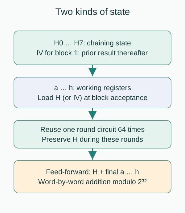
The first block starts from these public, fixed initial values. Later blocks load the H produced by the preceding block’s feed-forward.
H0 = 6a09e667   H1 = bb67ae85
H2 = 3c6ef372   H3 = a54ff53a
H4 = 510e527f   H5 = 9b05688c
H6 = 1f83d9ab   H7 = 5be0cd19
Why not update H every round? At the end, you need H0 plus final a, H1 plus final b, and so on. Overwriting H loses that baseline. In this architecture, ROUND updates only a–h; a separate ACCUM stage updates H.
6. The building blocks: rotations, selection and addition
SHA-256 has no AES S-box. Its main operations are fixed rotations, logical shifts, XOR, AND, NOT and addition. Every addition is modulo 2³²: keep only the low 32 bits. These additions have carries; XOR is not a substitute.
ROTRⁿ(x) wraps displaced low bits into the high positions; SHRⁿ(x) inserts zeros at the high end. A fixed rotation is typically wiring. A generic variable rotation may infer an unnecessary selection network.
// Fixed ROTR^7 and SHR^3; x is an unsigned 32-bit signal.
assign r7 = {x[6:0], x[31:7]};
assign s3 = x >> 3;| Function | Definition | Purpose |
|---|---|---|
| Ch(x,y,z) | (x & y) ^ (~x & z) | At each bit, x selects y or z |
| Maj(x,y,z) | (x & y) ^ (x & z) ^ (y & z) | Bitwise majority |
| Σ0(x) | ROTR² ⊕ ROTR¹³ ⊕ ROTR²² | Round input a |
| Σ1(x) | ROTR⁶ ⊕ ROTR¹¹ ⊕ ROTR²⁵ | Round input e |
| σ0(x) | ROTR⁷ ⊕ ROTR¹⁸ ⊕ SHR³ | W schedule |
| σ1(x) | ROTR¹⁷ ⊕ ROTR¹⁹ ⊕ SHR¹⁰ | W schedule |
Uppercase Σ and lowercase σ are different functions. The smaller sigmas include a shift as well as different rotation amounts. Names such as big_sigma0 and small_sigma0 prevent a very easy wiring mistake.
Begin with a single set bit to check that rotation wraps while shifting inserts zeros. Then use an overflowing sum to check that the circuit discards bit 33. Separate tests help distinguish wiring mistakes from arithmetic mistakes when a digest later disagrees.
Learn the operations with small values
Every hex value here is 32 bits. ROTR¹(00000001)=80000000: the low one wraps to the highest position. SHR¹(00000001)=00000000 discards it. Modular addition ffffffff + 00000001 = 00000000 retains the low 32 bits; XOR instead produces fffffffe. They are not interchangeable.
Ch selects independently at each bit: x=1 chooses y, and x=0 chooses z. For x=ffffffff, y=12345678 and z=9abcdef0, Ch=y; with x=00000000, Ch=z. Maj also works per bit: at least two of the three input bits must be one. It does not vote on eight whole-word integers. Return to abc below and calculate its first round from the complete IV.
7. One round: compute T1 and T2, then update together
Treat a round as a combinational function of the current a–h, W[t] and K[t], with t=0…63. K contains 64 public 32-bit constants, including K[0]=428a2f98 and K[63]=c67178f2. The full table appears in FIPS 180-4 §4.2.2 and the downloadable model.
T1 = h + Σ1(e) + Ch(e,f,g) + K[t] + W[t]
T2 = Σ0(a) + Maj(a,b,c)

a_next = T1 + T2      e_next = d + T1
b_next = a           f_next = e
c_next = b           g_next = f
d_next = c           h_next = g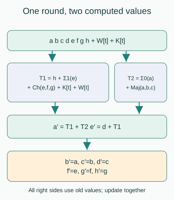
Every right-hand side uses the same old state. Overwriting a before assigning b would give b the wrong value. Nonblocking assignments describe registers sampling together at one rising edge.
// Conceptual ROUND branch; t1 and t2 are combinational 32-bit signals.
a <= t1 + t2;
b <= a;
c <= b;
d <= c;
e <= d + t1;
f <= e;
g <= f;
h <= g;
The connected logic responds whenever register outputs change; the clock decides when to capture the next values. T1 combines several addends, so investigate its delay rather than assuming rotations dominate timing. This schedule assumes combinational K lookup. A synchronous ROM needs look-ahead addressing or another stage, which changes the cycle contract.
Derive the first abc round from old values
All values are hexadecimal; each sum keeps its low 32 bits. Round 0 starts from the IV in section 5, with W0=61626380 and K0=428a2f98. Apply the rotations in section 6:
Σ1(510e527f)=3587272b; Ch(510e527f,9b05688c,1f83d9ab)=1f85c98c.
Thus T1 = 5be0cd19 + 3587272b + 1f85c98c + 428a2f98 + 61626380 = 54da50e8 (mod 2³²). Likewise, Σ0(6a09e667)=ce20b47e and Maj(6a09e667,bb67ae85,3c6ef372)=3a6fe667, producing T2=08909ae5.
Then a_next=54da50e8+08909ae5=5d6aebcd and e_next=a54ff53a+54da50e8=fa2a4622 (mod 2³²). b_next takes old a=6a09e667, not new a=5d6aebcd. This is a reproducible check of simultaneous updates.
Load abc in the laboratory. LOAD shows the IV; the next step, ROUND t=0, shows these T1/T2 and new a/e values. It corresponds to E1 in section 11; LOAD is E0. Comparing only the digest loses the chance to locate a fault in the formula versus register updates.
8. W scheduling: sixteen inputs feed sixty-four rounds
The block initially supplies W[0]…W[15]. Generate the remaining words using:
W[t] = σ1(W[t-2]) + W[t-7] + σ0(W[t-15]) + W[t-16]One implementation stores all 64 words and expands before processing, at the cost of preparation cycles or a larger combinational network. Our design instead uses a 16-word sliding window, storing 512 bits while generating future words in parallel with the current round.
At the start of round t, q[0] supplies W[t]. During the first 48 rounds, q[1], q[9] and q[14] contain W[t+1], W[t+9] and W[t+14]. Therefore:
next_w = σ1(q[14]) + q[9] + σ0(q[1]) + q[0]
round_w = q[0]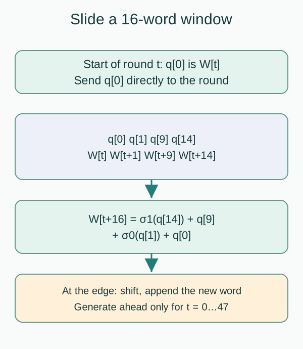
At the ending edge, shift q[1] into q[0] and so on, then append next_w in q[15]. Round t=0 generates W16; t=47 generates W63. For t=48…63 no further words are needed, so append zero while consuming the existing W48…W63 from the front.
// Inside ROUND; load all 16 words separately at block acceptance.
for (int j = 0; j < 15; j++) q[j] <= q[j+1];
q[15] <= (round_t < 6'd48) ? next_w : 32'b0;
All right-hand sides use the pre-shift window. Shifting before computing next_w moves every tap by one position. Test the scheduler independently: compare every consumed word against a full 64-word expansion, not just the final digest.
Derive W16 from the same padded abc block
For abc, W14=W9=W1=0 and W0=61626380. Substitute into the expansion: W16=σ1(W14)+W9+σ0(W1)+W0=0+0+0+61626380=61626380. At t=0, window taps q14,q9,q1,q0 contain exactly these values. The parallel next_w calculation therefore agrees. E1 inserts it into q15. Fifteen further shifts bring it to q0 after E16. Round t=16 consumes it for capture at E17.
W16 does not always equal W0; abc’s three zero terms make this a special case. Load the 56-byte example and inspect that block’s W1,W9,W14 before calculating W16. Figure taps, RTL q indices and the downloadable model’s expanded W array must agree on the consumed word.
9. Feed-forward connects blocks
After 64 rounds, a–h are still working results, not the final digest. Add them back word by word:
H0_new = H0_old + a_final    H4_new = H4_old + e_final
H1_new = H1_old + b_final    H5_new = H5_old + f_final
H2_new = H2_old + c_final    H6_new = H6_old + g_final
H3_new = H3_old + d_final    H7_new = H7_old + h_final
These are eight independent modulo-2³² sums, not one 256-bit addition with carries crossing word boundaries. Our separate ACCUM cycle reads the working state after t=63 has completed.
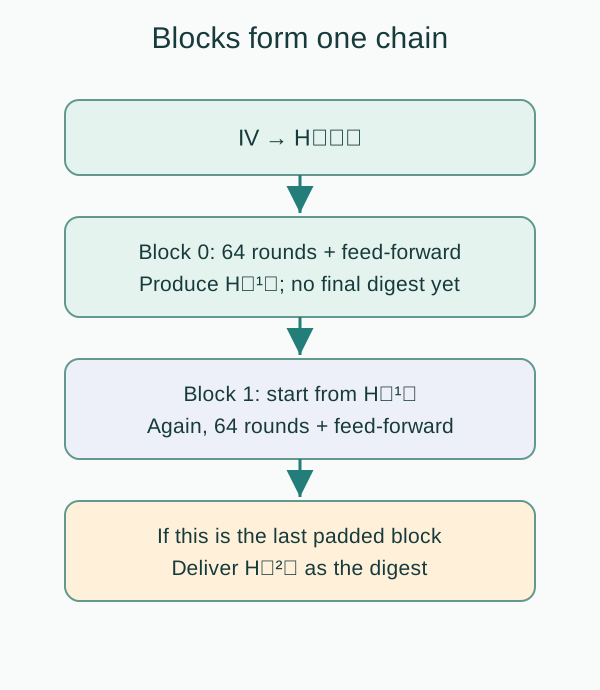
If another block follows, retain the new H. If this was the last block, deliver {H0,H1,…,H7}, with H0 in digest[255:224]. Blocks of one message are dependent: the next block needs the previous block’s accumulated state.
Sending two blocks of one firmware image to independent cores and joining their digests would compute something else. H connects successive blocks of this message. The first flag requests a return to IV only when a new message begins.
See feed-forward in the first digest word
After abc’s 64th round, a_final=506e3058. Original H0=6a09e667 remains intact, so H0_new=6a09e667+506e3058=ba7816bf. That is the digest’s first word. Outputting a_final directly would start with the wrong 506e3058. Combining all words into one 256-bit addition would also wrongly propagate carry between words.
Stop at the last ROUND in the laboratory, inspect working values, then advance to ACCUMULATE and compare H base with H next. The next block’s LOAD must use H next. This connects algorithm state; stepping the display does not measure actual RTL latency.
10. Define the block interface before the controller
The first core omits AXI, DMA and arbitrary-bit-length streaming. Upstream prepares padded blocks and provides first/last flags. The block and both flags are accepted together only at a rising edge with block_valid && block_ready.
| Signal | Direction | Width | Contract |
|---|---|---|---|
| clk, rst_n | In | 1 each | Rising edge; active-low synchronous reset |
| block_data | In | 512 | Already padded; B0 in the highest byte |
| block_first, block_last | In | 1 each | First / last padded block of the message |
| block_valid | In | 1 | Data and flags are valid |
| block_ready | Out | 1 | Core can accept at this edge |
| digest_data | Out | 256 | H0 in the highest word |
| digest_valid | Out | 1 | Final-block feed-forward has completed |
| digest_ready | In | 1 | Consumer can accept the digest |
| busy | Out | 1 | High in ROUND, ACCUM and OUTPUT_HOLD |
Use five states: WAIT_FIRST, WAIT_NEXT, ROUND, ACCUM and OUTPUT_HOLD. This design rejects an out-of-sequence first flag by withholding ready:
block_ready = rst_n && (
    (fsm == WAIT_FIRST && block_first) ||
    (fsm == WAIT_NEXT  && !block_first)
)
digest_valid = rst_n && (fsm == OUTPUT_HOLD)
The producer must present valid, data and first before waiting for ready. WAIT_FIRST accepts only first=1; WAIT_NEXT accepts only first=0. An invalid flag sequence is not consumed. This is a simple contract, not an error-reporting interface; assertions and timeouts should catch a violating source.
first=last=1 means a single-block padded message. Latch last at input acceptance; do not reread the external block_last after 64 rounds. In WAIT_NEXT, busy=0 means the core can accept the continuation, not that the whole message is finished.
While valid is high and no handshake has occurred, hold data, first, last and valid stable. Ready depends combinationally on first in this design; do not derive first from ready in the wrapper and create a combinational loop.
11. Exact timing: sixty-four rounds do not mean delivery in sixty-four cycles
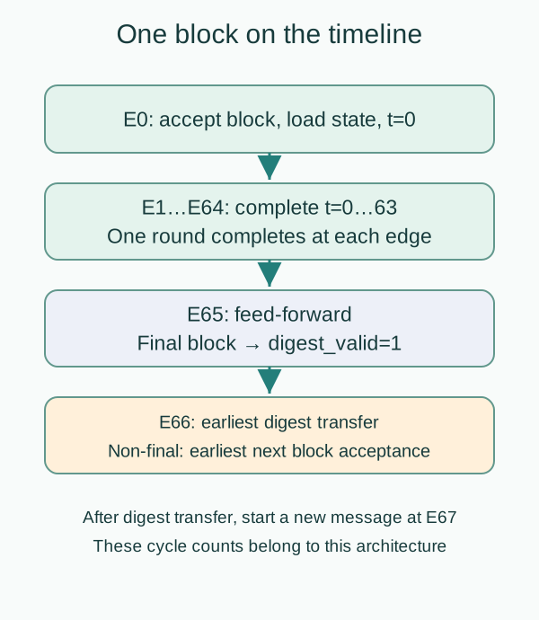
E0 is the block-acceptance edge. The following states are values after each edge. For the first block, load both H and a–h directly from IV. For a continuation, preserve H and load it into a–h. In both cases, load the sixteen input words into q and set t=0.
| Edge | Action | State after edge |
|---|---|---|
| E0 | Accept block, load H/work/q, t=0 | ROUND |
| E1–E63 | Complete t=0–62; update work and q | ROUND; increment t |
| E64 | Complete t=63; hold counter at 63 | ACCUM |
| E65, last=0 | Add work back into H | WAIT_NEXT |
| E65, last=1 | Add work back; digest_valid=1 | OUTPUT_HOLD |
| E66 or later | Accept continuation, or transfer final digest | ROUND or WAIT_FIRST |
| E67 or later | Earliest new message if digest transferred at E66 | ROUND |
The E66 transitions require successful handshakes. Without a continuation, stay in WAIT_NEXT; without output acceptance, stay in OUTPUT_HOLD. E0 only loads: do not also execute t=0 or shift q. ACCUM must not bypass OUTPUT_HOLD just because digest_ready is high. Select actions from the current FSM state to avoid conflicting updates.
Final-block acceptance to digest_valid is 65 cycles; earliest digest transfer is E66. Unstalled continuation blocks are accepted every 66 cycles, giving a long-message block-processing rate of approximately 512 × f_clk / 66 bits/s before padding and interface overhead. Consecutive single-block messages have a minimum acceptance interval of 67 cycles, not 66.
This assumes one round per cycle, combinational constant lookup, eight simultaneous feed-forward sums and no extra input/output pipeline. Shared adders or extra register stages require a new schedule. Obtain achievable f_clk from implementation and timing analysis, not from the algorithm’s round count.
12. Backpressure, reset and state that is easy to forget
Finishing the calculation means the core has an answer; it does not mean the consumer has taken it. While digest_valid=1 and digest_ready=0, hold H, digest_data and digest_valid. Do not accept another block that could overwrite H.
A rising-edge handshake completes the transfer and returns to WAIT_FIRST. This core does not accept a new message at that same edge, which explains E67. That gap is an interface choice, not a mathematical requirement of SHA-256.
At a rising edge with rst_n low, clear H, a–h, q, counter and latched last; return to WAIT_FIRST and cancel the incomplete message. Ready/valid are low during reset. After release, the first request must have first=1. Do not continue the canceled message. Clearing to zero does not replace the SHA IV: the first block acceptance explicitly loads IV.
The producer must also recognize that the message was canceled. If it offers a continuation, the core withholds acceptance; that wait is not slow hash computation. Flush the canceled scoreboard expectation and require a complete new message from the source.
Keep the roles of data registers, round counter and FSM visible. A single clear sequential block can update them, but each stage’s enables and next values must be traceable. Assign every combinational output completely to avoid unintended latches.
13. Find the first mismatch with abc
An output that looks random is not evidence of correctness. The NIST SHA-256 worked examples provide every a–h state for abc and a two-block message.
Input bytes   = 61 62 63
W0            = 61626380
W1 … W14     = 00000000
W15           = 00000018
K0            = 428a2f98

After t=0:
a=5d6aebcd  b=6a09e667  c=bb67ae85  d=3c6ef372
e=fa2a4622  f=510e527f  g=9b05688c  h=1f83d9ab

Final digest:
ba7816bf8f01cfea414140de5dae2223
b00361a396177a9cb410ff61f20015ad
The two digest lines form one continuous 64-digit hexadecimal string. NIST’s t=0 means after the first round, matching E1 here, not E0 initialization. Align sampling points before comparing traces.
| First mismatch | Investigate |
|---|---|
| W0 | Original bytes, padding, endianness |
| W16 after correct W0–W15 | Sigma variants, taps, pre/post-shift order |
| First-round a/e with correct W | K0, Ch/Maj, big sigmas, 32-bit sums |
| Correct first round, later offset | Counter, ROM latency, register updates |
| All rounds correct, digest wrong | Feed-forward, old H, cross-word carry |
| Short messages pass, long ones fail | Reloading IV per block, flags, padding boundary |
| Values correct, transaction count wrong | Lost valid or duplicate output under stalls |
14. Executable reference and verification exercises
Download the Node.js reference model and abc traces plus boundary results. Run:
node sha256-rtl-reference.mjs sha256-trace.jsonThe model independently expands a full W array, checks every word consumed by the sliding window, and compares its digest with Node/OpenSSL SHA-256. Its 271 messages cover empty input, abc, the NIST two-block message, 55/56/63/64-byte boundaries and varied byte patterns. The first abc round is also checked against NIST. This verifies the reference algorithm and schedule, not an RTL implementation.
In your testbench, supply already-padded blocks and record transfers only at valid/ready edges. Extend numerical checks with:
- Empty, one-, two- and three-block messages, including gaps before continuations.
- Always-ready output, then randomly stalled output; data and valid must hold.
- A different message immediately after completion; its first block must start from IV.
- Reset during ROUND, ACCUM and OUTPUT_HOLD; flush canceled scoreboard expectations.
- first=0 in WAIT_FIRST and first=1 in WAIT_NEXT; neither request may be consumed. Use a timeout.
- Every W[t], every a–h state and every block’s accumulated H, before the final digest comparison.
15. Module boundaries and an implementation order
| Module | Responsibility | First check |
|---|---|---|
| sha256_round | Old a–h, Wt, Kt → next a–h | NIST t=0, then all rounds |
| sha256_schedule | Load and maintain the 16-word window | All 64 consumed words |
| sha256_constants | t → Kt | All constants and lookup latency |
| sha256_core | H/work/q, FSM, handshakes, accumulation | Multiple blocks, stalls, reset |
| Message wrapper, later | Bytes, length, padding, first/last | 55/56-byte boundary and stream stalls |
Build the combinational round, then the scheduler, then storage and control. Adding AXI, DMA, padding, SHA-224 selection and a deep pipeline together makes failures harder to isolate. Every shared resource or new stage changes the timing argument you must verify.
This order separates questions. Round tests check the equations; scheduler tests check which W each round consumes. Once both pass independently, integration tests can focus on loading, accumulation and delivery. Comparing only the final digest mixes numerical and control failures.
Data storage here includes 256 bits of H, 256 bits of work and 512 bits of q: 1024 bits, plus counter, flags and control. The K table contains 2048 constant bits; a combinational implementation does not necessarily use 2048 flip-flops. Once the first core works, use synthesis reports to investigate adder critical paths, area and switching power.
16. What should you be able to explain now?
- A message wrapper is necessary because the block core does not infer message length or padding.
- H stays unchanged during rounds because feed-forward needs the block’s starting H.
- K is a shared public constant table, unlike an AES round key.
- The final block becomes valid at E65 because feed-forward follows the 64 rounds.
- An original 64-byte message still needs another padded block.
Back in the firmware system, this core establishes the numerical digest. Signature verification and trusted boot policy use that digest in a larger decision. HMAC also needs key processing and inner/outer hashing; connecting a key to this core’s K input does not create HMAC.
17. References and design scope
- FIPS 180-4: §4.1.2 functions, §4.2.2 constants, §5.1.1 padding, §5.3.3 IV, §6.2 SHA-256.
- NIST SHA-256 worked examples: round-by-round single- and two-block cases.
- NIST publication page: document version and status.
The sliding window, five-state FSM, first-flag rejection policy and E0–E67 schedule are teaching architecture choices, not a mandated standard interface or a performance promise for a particular process.
Streaming padding, AXI/DMA and concurrent messages remain outside this first core. Timing closure, side channels and fault defenses need separate validation too. Build a message wrapper next, or read RTL Anti-Tampering Lesson 1 to examine how a digest participates in authorization.
MY ACADEMY · LESSON FILM
Lesson video
The film explains this lesson’s data path. After a section, return to the interactive exercise and change the input or fault conditions. The animation presents a teaching model; it does not replace RTL simulation.
Narration uses a synthetic voice. Both the interaction and animation have model boundaries; interpret results using this lesson’s sources and validation scope.
MY ACADEMY · RTL LAB
Operate SHA-256: follow blocks and round registers
Start with abc at round 0 and inspect W, K, T1, T2 and a–h. Load the 56-byte example to see why padding creates two blocks and how the previous block updates H.
The teaching schedule has LOAD, 64 ROUND updates and ACCUMULATE. LOAD and ACCUMULATE are separate steps. Actual RTL latency depends on its FSM, schedule and interface.
Evidence scope: a browser functional teaching model. Independent comparison uses browser Web Crypto. No RTL simulation, synthesis, formal proof or side-channel testing is performed.
Before operation
After operation
Inspect blocks, schedule and round keys
Output handshake: valid / ready
At OUTPUT, the output remains stable. Set ready, then sample an edge to record acceptance. Changing ready alone does not accept data. This handshake is a separately defined teaching interface.
Transfer exercise: may RTL clear output_valid or overwrite the result before downstream is ready? State the hold rule in plain language: unless reset cancels the transaction, valid and data remain stable until a handshake. SVA syntax is an optional next exercise.
Learning guide
Cryptographic RTL Design
Open the course outline → · Progress counts published lessons only
Prerequisites
- Synchronous registers, bitwise operations and basic Verilog
What I learned
- Separate message preparation from the block core
- Build and verify the 16-word schedule
- Coordinate 64 rounds, feed-forward and block chaining
- Specify cycle timing, backpressure and reset